This blog contains several Electrical Motor Control Wirings, and Operations.

  • Delayed Automatic Forward Reverse Motion of Overhead Crane Driven by a Motor

    This is another situation that requires the overhead crane to rest for a while upon reaching both of the rail. After a pre-determine time the overhead crane will re-start in the opposite direction.

  • Limiting the Forward and Reverse Motion of an overhead crane driven by a motor

    The motion of an overhead crane moving forward and reverse can be automatically stop at both end by placing a limit switches X and Y in the control circuit of the Forward – Reverse Motor Control shown in Figure below (d).

  • Automatic Forward and Reverse Motion of Overhead Crane Driven by a Motor

    Notice that when contact (1-2) of limit switch X opens to de-energized contactor F, its contact (1-3) will almost simultaneously closed to energized the contactor R. This will bring about the automatic reversal of the overhead crane from the left to the right.

  • Forward Reverse Motor Control

    The forward reverse motor control is used i a system where forward and backward or upward and downward movement in the operation are needed.

  • WYE-DELTA REDUCE VOLTAGE STARTER

    Some motors starters at high current more than several times its current at full load condition. The effect of this to other is necessary tripping of circuit breakers. One way of reducing the high starting current of a motor is the start the motor with the low voltage at its winding. After a few seconds, when the motor is already running at its stable condition, the rated full voltage is applied to its winding. This system is called reduced voltage starting.

Monday, 30 January 2017

TAPS, SPLICES AND JOINTS

Method of Skinning Electrical Wire


Removing the insulation in preparing the insulated conductors for making joints or splices, the insulation must first be removed from each conductor a proper distance depending upon the type of joint or splice to be made.
This process is called skinning or stripping.

Cleaning the Conductor


After removing the insulation, the wires must be thoroughly cleaned to ensure good electric contact between the ends of the wires so that the solder will adhere properly. The wire may be cleaned by scraping.

Different electrical wires, splices and joints

Types of taps, Splices and Joints of Conductor


Rat tail joints are used to join conductors in outlet boxes or when fixture leads are connected through conductors. The joints are made by skinning about 2 inches, the end of the conductor is to be joined. Then twist the bare conductors about six times.

TAPS, SPLICES AND JOINTS


Western Union Short tie splice - To make the splice, the wires are first skinned for about 3 inches at the ends. They are then placed in crossed position about 1 inch from the insulation. Four or five short turns are then wrapped on each side of the longest twist, and the free ends cut off and squeezed down closed to the straight position of the wire so that they will not extend over the surface of the short turns and permit the sharp to cut through the tape with the splice to be wrapped.

Western Union Short tie splice


Western Union Long Tie Splice is used extensively for outside wiring and is quite similar to the short tie splice. It is also being used for interior wiring. The difference is that a number of long twist are made before wrapping the end turns. This is done so to withstand greater stress of pressure on the wire. The wire for this splice are bared about 4 ½ inches. They are then placed in the form of an X at a point midway between the insulation and the end of the base wire. Five or six long twists are then made and each side those turns are wrapped.

TAPS, SPLICES AND JOINTS


Britannia Splice is used in interior wiring where solid wires of No. 6 AWG gauge or larger sizes are to be joined and where large wire connectors or pliers are not at hand. The two wires are based for about 4 inches in a No. 6 wire. About ½ inch of the extreme end of each beat to almost a right angle to the straight portion of the conductor. A wrapping wire made of No. 18 bare wire copper is then cut to about 6 ft. in length and prepared by cleaning and bending in half. The large conductors are then laid together, one bent end pointing upward and the other downward. The center of the wrapping wire is then brought to the center of the conductor, one half of which is wrapped in one direction and other remaining half in the other as far as the best portion. The free ends are then forced through the grooves from one ends to the other end of the other of the large single conductors. The best ends are then cut off close to the joint.

TAPS, SPLICES AND JOINTS


Scarfed splice. It is used only on a large solid wire where there is an objection to the bulkiness of the Western Union or Britannia splice. The wires are bared for about 3 inches when a No. 6 wire is used.
The bared wire is then filed to a wedge shape starting about ½ inch from the insulations. A piece of No. 18 bare copper wire is cut to about 5 ft. in length and prepared by cleaning and bending in half.
The two file sides of the conductors are then laid together and wrapping wire wound around them as similarly done in Britannia Splice. The wrapping is completed by winding about six and seven turns of the free ends around the unfilled portion of the conductor.

TAPS, SPLICES AND JOINTS


Multiple wrapped cable splice is used more extensively on small strand wires and cables because these stands are more pliable and may be wound together without much difficulty. Large strands are rigid and require considerable time in making such a splice. To make the splice, the ends of the conductors are skinned at the distance of about 6 inches. The strands are cleaned and spread about apart. Next, the strands are cut about 3 inches from the insulation to right angle with the conductor. The strands of both conductors are then laced together, one group of strands wounds in the opposite direction. Care should be done that all strands in each group are wrapped simultaneously and parallel to one another.

TAPS, SPLICES AND JOINTS


Plain tap or Tee Joints is used to a great extent joining a tap or other conductor to a through conductor, as for example, a branch or main circuit. To make the joint, skin the tap wire about 2 inches and the main wire about 1 inch. Next, the wires are crossed intersecting about ¼ inch from the insulation of the tap wire and the main wire. A hook or sharp bend is then made in the tap and about five or six turns wound around the main wire. The joint is soldered and tape. Care must be taken that the solder flows and sticks through all the crevices and that the tape covers all part of the conductors, beginning and ending on the original insulation.

TAPS, SPLICES AND JOINTS


Knotted or loop, tap joint is very strong joint and will not untwist even enough strain is placed upon it. It is occasionally used in practice, particularly for temporary lighting systems, where time is not taken to solder joints. To make the join using No. 14 AWG wire, the tap wire is skinned about 3 inches and is then placed over the insulation of the tap and main wire. The tap wire is bent and hooked over the main wire and brought forward and bent over itself. Lastly, the remaining portion is wound into four or five short turns around the main wire.

TAPS, SPLICES AND JOINTS


Wrapped Tap, Tee Joint is used on large solid conductors where is difficult to wrap the heavy tap wire around the main wire. When a No. 6 AGW wire is used, both the main wire and the tap wire are skinned about 4 inches. The tap wire is bent into an L shape about ½ inches from the insulation so that it will rest along the side of the main wire. A wrapping wire is then prepared using size No. 18 bare conductors terminating beyond the bent of tap wire and up to the installation of the main conductor.

TAPS, SPLICES AND JOINTS


Ordinary Cable Tap or Tee Joint is used where large stranded wire or cables are tapped to a through conductor. To make the joint, the main strands should be scraped through with a knife blade or sandpaper. The tap wire of similar wire size cable should be skinned about 6 inches distance and the strands separated or fanned each strands of the tap into the shape. The main cable is placed into this V-shaped space and forced down to within 1 inch from the insulation of the tap conductor. One group of tap wires is then wound around the main conductor, each strands should be placed parallel to the other, and all wrapped at the same time and in one direction. The other group is wound in similar manner but in opposite directions.

TAPS, SPLICES AND JOINTS


Split Cable Tap or Tee Joint is used where stranded cables or wire are tapped to a through conductor. This joint is stronger than the ordinary cable tap and will not unwrap even though a strain is placed upon it prior soldering. To make this joint, the main wire is skinned a distance of 5 inches No. 14 American Wire Gauge (AWG) wire size is used and the strands thoroughly scraped as for the ordinary cable tap. The strands are next divided in half by forcing the screw driver through the center of the bared portion of the main wire. The tap wire is prepared by skinning it about 6 inches, scraping each strand until thoroughly cleaned and fanning out the strands so that they can be pushed around the space in the main wire. A space about 1 ½ inch should be left between the main wire and the insulation of the tap wire. In completing the joint, one group is wound around the main conductor, in one direction; and the second group is wound in the opposite direction.

TAPS, SPLICES AND JOINTS


The Through Fixture Joint is used where fixtures are connected to branch wires at an intermediate point. In making this joint, the end of one conductor is skinned about 2 inches and the other about 4 inches. At a point ¼ inches away from the insulation of the longer wire, three or four long twists are made similar to the rat-tail joint. The long bared portion of the long wire is bent over parallel with the free ends. Both free ends are then place alongside each other wrapped together around the straight bared portion.

TAPS, SPLICES AND JOINTS


Safety procedure in splicing and joining wire


Before the splice is made, the insulation is first removed on both ends with the use of an electrician’s knife or diagonal pliers. An electrician should be very careful in removing wire insulation in order that the wire will not be nicked by the knife or pliers to prevent breaking. However, a specially designed tool to avoid nicks is called automatic wire stripper. The function of the tool is to cut the wire insulation and remove it automatically by inserting the wire corresponding to the size of hole in the wire stripper. After removing the insulation, the end of the wire is twisted firmly. When the joint has been made, the correct practice is to solder it to prevent loose contact and to have a continuous flow of electricity. The splice and joint are then covered properly with an electrical tape in order to prevent short circuit.
Share:

Saturday, 21 January 2017

HISTORY OF ELECTRICITY

Electricity plays an important role in man’s conquest for existence .It has been said that it is here with us since the beginning of the time.

In 600 B.C, Thales a Greek philosopher accidentally discovered static electricity. Noticing that his garment had bits of hair and straw, Thales decided to remove them by rubbing piece of amber stone on his clothes. To his surprise, several pieces of straw clung to the amber when rubbed on the clothes, the amber became electrified and it attracted the pieces of straw. Thales simply wrote the incident and did not do anything about it because he could not explain the mystery. He did not know that he had just discovered static electricity.

In 1600, William Gilbert, an English Physician was able to put an electrical charged on the objects by means of friction or rubbing. He observed that two materials when rubbed together received opposite charges, that is, one object got a positive charge and the other a negative charge. He also noticed that two oppositely charged materials attract each other. Gilbert experiment was a re-discovery of static electricity, the word static means standing still or at rest. The Greek word for amber stone is “ ELEKTRON” and so the term electricity came about.


Great persons who involved in the discovery of electricity:


1760- Benjamin Franklin, An American scientist, proved that atmospheric electricity (lightning) and static electricity are the same.
1800- Alessandro Volta, An Italian Professor, discovered the voltaic file by means of stocking zinc plate (-) and silver plate (+).
1819- Hans Christian Oestered, A Danish Physicist proved in an experiment that current electricity can produced a magnetic field.
1831 Michael Faraday, An English scientist discovered the first electric generator.
1831- Samuel Morse, developed the telegraph.
1868-George de Clanche, developed the first practical dry cell.
1878-Charles Brush, invented the arc lamp
1879- Thomas Alba Edison, perfected the first electric bulb


Sources of electricity


1. Friction -It is a static electricity which is generated by rubbing two materials.
2. Chemical action - It is a great deal of the world’s electricity produced by batteries. These devices generate a different potential means of chemical action.
3. Heat action - Two dissolution metals bonded together in a junction when heated, exhibits a difference of potential. Such bond is called thermocouple. The trip of an iron wire, for example, may be welded to that of a copper wire. When, this junction is heated, the iron wire shows a positive charge and the copper wire has a negative charge. Electricity generated by heat action is called thermoelectric.
4. Light action - Photo cells are semi-conduction devices which convert light electrical energy directly into electrical energy. Either sunlight or artificial illumination may be employed. This action is due to the ability of lights energy to free electrons from the atoms of the semi-conductor material. This process is called photo-electricity.
5. Pressure - It is a difference of potential appears across the face of certain crystal such as quarts, when they are squeezed or stretched. This is called piezo-electricity.
6. Mechanical action - All electricity in large useful amount is at present produced by rotating machines working with the use of magnets. These machines, known as generator, are turned by water power, gas engines or steam engines and sometimes by electric motor.

There are many different types of mechanical power plants to produce electrical energy.

Hydropower is an energy obtained from flowing water. Energy in water can be harnessed and used in the foot motive energy or temperature differences. The most common application is the dam.
Power produced by the fall of water from a higher to a lower level and extracted by means of waterwheels or hydraulic turbines. Hydro-power is a natural resource available wherever a sufficient volume of steady water flow exists.

Hydropower is an energy obtained from flowing water. Energy in water can be harnessed and used in the foot motive energy or temperature differences.

Nuclear Power is the method in which steam is produced by heating water through a process called nuclear fission. In a nuclear power plant, a reactor contains a core of nuclear fuel, primary enriched uranium. When atoms of uranium fuel are hit by neutrons they fission (split), releasing heat neutrons.
Nuclear power is an electrical power produced from energy released by controlled fission or fusion of atomic nuclei in a nuclear reaction. Mass is converted into energy and the amount of released energy greatly exceeds that from chemical processes such as combustion.

Nuclear Power is the method in which steam is produced by heating water through a process called nuclear fission.

Solar Power is a power derived from the energy of the sun. A radiant energy produced in the Sun as a result of nuclear fusion reactions. It is transmitted to the earth through space by electromagnetic radiation in quanta of energy called photons which interact with the earth’s atmosphere and surface.

Solar Power is a power derived from the energy of the sun. A radiant energy produced in the Sun as a result of nuclear fusion reactions.


Wind Power is the kinetic energy of wind or the extraction of this energy by wind turbines. Windmill machine converts wind into useful energy. This energy is derived from the force of wind acting on oblique blades or sails that radiate from a shaft. The turning shaft may be connected to machinery used to perform such work as milling grain, pumping water, or generating electricity. When the shaft is connected to a load, such as a pump, the device is typically called a windmill. When it is used to generate electricity, it is known as a wind turbine generator.

Wind Power is the kinetic energy of wind or the extraction of this energy by wind turbines. Windmill machine converts wind into useful energy.


Fossil Fuel Power Plant (FFPP) – (also known as steam electric power plant in the US, thermal power plant in Asia, or power station in UK). The most common source of energy is fossil fuel. Fossil fuels include coal, oil, and natural gas. Fossil fuel is formed from the remains of plant and animals which live thousands of years ago. The burning of those fossil fuel provides energy which can be used to generate electricity.

Fossil Fuel Power Plant (FFPP) – (also known as steam electric power plant in the US, thermal power plant in Asia, or power station in UK).


Geothermal power comes from heat energy buried beneath the surface of the earth. In some areas of the country, enough heat rises close to the surface of the earth to heat underground water into steam which can be tapped for use in steamturbine plants. Geothermal Power is the energy extracted from the heat generated by natural concentrations of hot water and steam in the earth’s interior. It can be used in electric power generation and direct heat applications such as space heating and industrial drying processes.

Geothermal power comes from heat energy buried beneath the surface of the earth. In some areas of the country, enough heat rises close to the surface of the earth to heat underground water into steam which can be tapped for use in steamturbine plants.


Tides is another kind of energy that involves water. Ocean tides can be used to turn turbines to generate electricity. For this to be possible, a dam must be built across the month of a bay. Water then in trapped behind the dam at the high tide. At the low tide, the water is allowed to run out through the dam and used to turn on electrical generator.

Tides is another kind of energy that involves water. Ocean tides can be used to turn turbines to generate electricity. For this to be possible, a dam must be built across the month of a bay.

Share:

PRINCIPLES AND THEORIES OF ELECTRON

Electricity is a property of the basic particle of matter which, like an atom, consists of proton, electron and neutron. The electron is the negatively charged particle of an atom which is sometimes referred to as the negatively charge of electricity. On the other hand, the proton is the positively charged particle of an atom which is sometimes referred to as the positively charge of electricity that weighs about 1850 times as much as the electron. The neutron is the particle which is not electrically charged and weighs slightly more than proton.

Molecular theory


1. All matters are made up of molecules.
2. All molecules are made up of atoms.
3. All the atoms contain neutron, electrons and protons.
5. The entire neutron is neutral, hence, neither positively nor negatively charged.
6. The electron of an atom of any substance could be transferred to another atom.

The electron theory


The electron theory states that all matter is made up of electricity. Matter is anything which has weight, occupies space is made up of molecules, of which millions of different kinds. The molecules in turn, are made up of atoms of which are the smallest units of the several elements and of a limited number. All atoms believed to be composed of electrons, which are minute particle of negative electricity normally held in place in each atom by positively charged particles called nucleus. Thus, the electron, which are interlocked in the atoms, are constantly revealing at great speeds in orbits around positive nuclei. In a normal atom, the amount of negative electricity of the electrons is exactly neutralized by an equal amount of opposite or positive electricity of the nucleus. Thus, a normal atom exhibits no external sign of electrification.

Structure of an atom


All atoms consist of two basic parts: a body at the center of the atom called the nucleus, orbiting around the nucleus. Atoms may have more than one orbiting electron, but each atom contains only one nucleus.

PRINCIPLES AND THEORIES OF ELECTRON

The attraction between the nucleus and the electron is called electrostatic force, which holds the electron in an orbit. Bodies that attract each other in this special electrostatic way are described as charged object. The electron carries the negative charge (-), while the nucleus carries the positive charge (+).

PRINCIPLES AND THEORIES OF ELECTRON


The positive charge of the nucleus is due to the particles called protons which are found inside the nucleus and have a positive charge equal to the electron’s negative charge.

PRINCIPLES AND THEORIES OF ELECTRON


The structure of neutrons in the atoms showing the position of its proton, electron, nucleus and neutron is shown below.

PRINCIPLES AND THEORIES OF ELECTRON


First Law of Electrostatics


The protons and electrons attract each other inside the atom. It has been known that by nature, unlike charges (like the positive protons and negative electrons) attract each other while like charges repel each other; meaning, electrons and protons repel each other’s protons.

PRINCIPLES AND THEORIES OF ELECTRON

Share:

Thursday, 12 January 2017

THREE PHASE AND SINGLE PHASE Induction Motors

Induction Motor


•      Induction motors are used worldwide in many residential, commercial, industrial, and utility applications.
•          Induction Motors transform electrical energy into mechanical energy.
•     It can be part of a pump or fan, or connected to some other form of mechanical equipment such as a winder, conveyor, or mixer.

THREE PHASE AND SINGLE PHASE Induction Motors


Construction


•          The three basic parts of an AC motor are the rotor, stator, and enclosure.
•          The stator and the rotor are electrical circuits that perform as electromagnets.

THREE PHASE AND SINGLE PHASE Induction Motors


Squirrel Cage Rotor

Squirrel Cage Rotor

Construction (Stator construction)


•          The stator is the stationary electrical part of the motor.
•          The stator core of a National Electrical Manufacturers Association (NEMA) motor is made up of several hundred thin laminations.
•          Stator laminations are stacked together forming a hollow cylinder. Coils of insulated wire are inserted into slots of the stator core.
•          Electromagnetism is the principle behind motor operation. Each grouping of coils, together with the steel core it surrounds, form an electromagnet. The stator windings are connected directly to the power source.

Construction (Stator construction)

Construction (Rotor construction)


•          The rotor is the rotating part of the electromagnetic circuit.
•          It can be found in two types:
–        Squirrel cage
–        Wound rotor
•          However, the most common type of rotor is the “squirrel cage” rotor.

 Construction (Rotor construction)

•          Induction motor types:
v                  Squirrel cage type:
Ø  Rotor winding is composed of copper bars embedded in the rotor slots and shorted at both end by end rings
Ø  Simple, low cost, robust, low maintenance
v   Wound rotor type:
Ø  Rotor winding is wound by wires. The winding terminals can be connected to external circuits through slip rings and brushes.
Ø  Easy to control speed, more expensive.

Construction (Rotor construction)


Wound Rotor

Wound Rotor


Squirrel-Cage Rotor


Squirrel-Cage Rotor


Construction (Enclosure)


•          The enclosure consists of a frame (or yoke) and two end brackets (or bearing housings). The stator is mounted inside the frame. The rotor fits inside the stator with a slight air gap separating it from the stator. There is NO direct physical connection between the rotor and the stator.

Construction (Enclosure)


•          The enclosure also protects the electrical and operating parts of the motor from harmful effects of the environment in which the motor operates. Bearings, mounted on the shaft, support the rotor and allow it to turn. A fan, also mounted on the shaft, is used on the motor shown below for cooling.

Construction (Enclosure)

Construction (Enclosure)


Nameplate Data

Nameplate Data

Manufacturer’s Type


Manufacturer’s Type


Rated Voltage


Rated Voltage


FLA(Full Load Amps)


FLA(Full Load Amps)


Rated Frequency


Rated Frequency


Full Load RPM


Full Load RPM


Insulation Class


Insulation Class


Ambient Temperature


Ambient Temperature

Time Rating(Duty)


Time Rating(Duty)


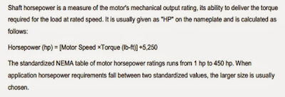
Horsepower Rating


 Horsepower Rating


Locked Rotor kVA Code


Locked Rotor kVA Code


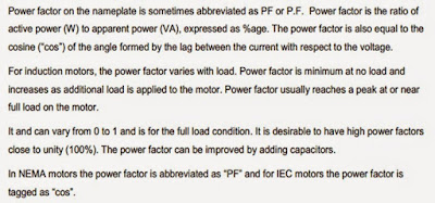
Power Factor


Power Factor


Service Factor


Service Factor


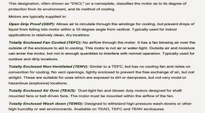
Enclosure Type


Enclosure Type


Nominal Efficiency


Nominal Efficiency


Frame Size


Frame Size


NEMA Design Letters


NEMA Design Letters


Rotating Magnetic Field


•          When a 3 phase stator winding is connected to a 3 phase voltage supply, 3 phase current will flow in the windings, which also will induced 3 phase flux in the stator.
•          These flux will rotate at a speed called a Synchronous Speed, ns. The flux is called as Rotating magnetic Field
•          Synchronous speed: speed of rotating flux

 Where;                 p = is the number of poles, and
                                                f  = the frequency of supply

Rotating Magnetic Field

AC Machine Stator

AC Machine Stator


Slip and Rotor Speed


•          The synchronous speed for a squirrel cage motor is calculated by multiplying the constant 120 times the electrical supply frequency; then dividing the result by the number of poles in the motor.
Synchronous speed = 120(frequency)
                                        no. of poles

Slip and Rotor Speed


The actual speed of a squirrel cage motor is less than its synchronous speed. This difference between actual speed and synchronous speed is called "slip.“

                                                                slip%= (syn-actual)(100)
                                                                                        sync

Slip and Rotor Speed


The design of a motor stator and rotor affect its slip characteristics. Squirrel cage motors are made with slip ranging from less than 5% to more than 20%. Motors with slip less than 5% are sometimes called normal slip motors. Motors with slips greater than 5% are used for hard to start loads, because of their inherent capability to create more torque.

Asynchronous and Synchronous Motor


In a typical AC motor, a rotating magnetic field is produced in the stator. The speed of this rotating field is called the synchronous speed and is determined only by the frequency of the power supply and the number of poles of the machine. A synchronous motor is one in which the rotor rotates at the same speed as the rotating magnetic field in the stator. An asynchronous motor is one in which the rotor rotates at a speed slower than the synchronous speed.

 Principle of Operation


Ø  When a 3 phase stator winding is connected to a 3 phase voltage supply, 3 phase current will flow in the windings, hence the stator is energized.
Ø  A rotating flux Φ is produced in the air gap. The flux Φ induces a voltage in the rotor winding (like a transformer).
Ø  The induced voltage produces rotor current, if rotor circuit is closed.
Ø  The rotor current interacts with the flux Φ, producing torque. The rotor rotates in the direction of the rotating flux.
Share:
Powered by Blogger.