Induction Motor
• Induction motors are used worldwide in many residential, commercial, industrial, and utility applications.
• Induction Motors transform electrical energy into mechanical energy.
• It can be part of a pump or fan, or connected to some other form of mechanical equipment such as a winder, conveyor, or mixer.
Construction
• The three basic parts of an AC motor are the rotor, stator, and enclosure.
• The stator and the rotor are electrical circuits that perform as electromagnets.
Squirrel Cage Rotor
Construction (Stator construction)
• The stator is the stationary electrical part of the motor.
• The stator core of a National Electrical Manufacturers Association (NEMA) motor is made up of several hundred thin laminations.
• Stator laminations are stacked together forming a hollow cylinder. Coils of insulated wire are inserted into slots of the stator core.
• Electromagnetism is the principle behind motor operation. Each grouping of coils, together with the steel core it surrounds, form an electromagnet. The stator windings are connected directly to the power source.
Construction (Rotor construction)
• The rotor is the rotating part of the electromagnetic circuit.
• It can be found in two types:
– Squirrel cage
– Wound rotor
• However, the most common type of rotor is the “squirrel cage” rotor.
Construction (Rotor construction)
• Induction motor types:
v Squirrel cage type:
Ø Rotor winding is composed of copper bars embedded in the rotor slots and shorted at both end by end rings
Ø Simple, low cost, robust, low maintenance
v Wound rotor type:
Ø Rotor winding is wound by wires. The winding terminals can be connected to external circuits through slip rings and brushes.
Ø Easy to control speed, more expensive.
Construction (Rotor construction)
Wound Rotor
Squirrel-Cage Rotor
Construction (Enclosure)
• The enclosure consists of a frame (or yoke) and two end brackets (or bearing housings). The stator is mounted inside the frame. The rotor fits inside the stator with a slight air gap separating it from the stator. There is NO direct physical connection between the rotor and the stator.
• The enclosure also protects the electrical and operating parts of the motor from harmful effects of the environment in which the motor operates. Bearings, mounted on the shaft, support the rotor and allow it to turn. A fan, also mounted on the shaft, is used on the motor shown below for cooling.
Construction (Enclosure)
Nameplate Data
Manufacturer’s Type
Rated Voltage
FLA(Full Load Amps)
Rated Frequency
Full Load RPM
Insulation Class
Ambient Temperature
Time Rating(Duty)
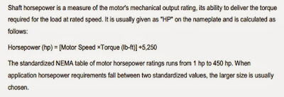
Horsepower Rating
Locked Rotor kVA Code
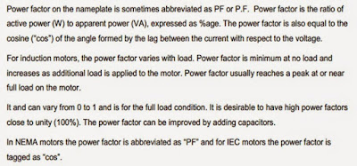
Power Factor
Service Factor
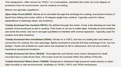
Enclosure Type
Nominal Efficiency
Frame Size
NEMA Design Letters
Rotating Magnetic Field
• When a 3 phase stator winding is connected to a 3 phase voltage supply, 3 phase current will flow in the windings, which also will induced 3 phase flux in the stator.
• These flux will rotate at a speed called a Synchronous Speed, ns. The flux is called as Rotating magnetic Field
• Synchronous speed: speed of rotating flux
Slip and Rotor Speed
• The synchronous speed for a squirrel cage motor is calculated by multiplying the constant 120 times the electrical supply frequency; then dividing the result by the number of poles in the motor.
Synchronous speed = 120(frequency)
no. of poles
Slip and Rotor Speed
The actual speed of a squirrel cage motor is less than its synchronous speed. This difference between actual speed and synchronous speed is called "slip.“
slip%= (syn-actual)(100)
sync
Slip and Rotor Speed
The design of a motor stator and rotor affect its slip characteristics. Squirrel cage motors are made with slip ranging from less than 5% to more than 20%. Motors with slip less than 5% are sometimes called normal slip motors. Motors with slips greater than 5% are used for hard to start loads, because of their inherent capability to create more torque.
Asynchronous and Synchronous Motor
In a typical AC motor, a rotating magnetic field is produced in the stator. The speed of this rotating field is called the synchronous speed and is determined only by the frequency of the power supply and the number of poles of the machine. A synchronous motor is one in which the rotor rotates at the same speed as the rotating magnetic field in the stator. An asynchronous motor is one in which the rotor rotates at a speed slower than the synchronous speed.
Principle of Operation
Ø When a 3 phase stator winding is connected to a 3 phase voltage supply, 3 phase current will flow in the windings, hence the stator is energized.
Ø A rotating flux Φ is produced in the air gap. The flux Φ induces a voltage in the rotor winding (like a transformer).
Ø The induced voltage produces rotor current, if rotor circuit is closed.
Ø The rotor current interacts with the flux Φ, producing torque. The rotor rotates in the direction of the rotating flux.


Hello Dear,
ReplyDeleteThank you for sharing beneficial blog. I read your blog about THREE PHASE AND SINGLE PHASE Induction Motors carefully. It is really brief introduction about 3 Phase Induction Motor and single phase introduction motor. You describe the all over introduction, construction and define all the parts of Induction with a brief detail. MM Engineering Services Ltd Your Blog is really an interesting & informative to read.
Lestov has been working on maximizing cooking efficiency in commercial induction technology since 2003. Lestov currently homes 200+ full-time employees, nominated and recommended by CCA and WFCCI (formerly WACC), partnering with 50+ countries and holds CE Certificates. Lestov
ReplyDeleteThe Orchid Dinex Commercial Induction Cook Top stands out as a premier choice for discerning restaurants, hotels, and cafes seeking culinary excellence and operational efficiency. Renowned for its advanced induction technology, Orchid Dinex offers superior heating precision, rapid temperature control, and remarkable energy efficiency, making it an ideal centerpiece for busy professional kitchens. Beyond its exceptional cooking capabilities, Orchid Dinex is also recognized as a leading supplier of high-quality crockery, providing establishments with the perfect complement to their culinary creations. Whether equipping a bustling restaurant, a sophisticated hotel kitchen, or a charming cafe, Orchid Dinex delivers a comprehensive solution, combining top-tier cooking equipment with elegant and durable tableware to elevate the entire dining experience.
ReplyDelete