This blog contains several Electrical Motor Control Wirings, and Operations.

  • Delayed Automatic Forward Reverse Motion of Overhead Crane Driven by a Motor

    This is another situation that requires the overhead crane to rest for a while upon reaching both of the rail. After a pre-determine time the overhead crane will re-start in the opposite direction.

  • Limiting the Forward and Reverse Motion of an overhead crane driven by a motor

    The motion of an overhead crane moving forward and reverse can be automatically stop at both end by placing a limit switches X and Y in the control circuit of the Forward – Reverse Motor Control shown in Figure below (d).

  • Automatic Forward and Reverse Motion of Overhead Crane Driven by a Motor

    Notice that when contact (1-2) of limit switch X opens to de-energized contactor F, its contact (1-3) will almost simultaneously closed to energized the contactor R. This will bring about the automatic reversal of the overhead crane from the left to the right.

  • Forward Reverse Motor Control

    The forward reverse motor control is used i a system where forward and backward or upward and downward movement in the operation are needed.

  • WYE-DELTA REDUCE VOLTAGE STARTER

    Some motors starters at high current more than several times its current at full load condition. The effect of this to other is necessary tripping of circuit breakers. One way of reducing the high starting current of a motor is the start the motor with the low voltage at its winding. After a few seconds, when the motor is already running at its stable condition, the rated full voltage is applied to its winding. This system is called reduced voltage starting.

Saturday, 21 January 2017

PRINCIPLES AND THEORIES OF ELECTRON

Electricity is a property of the basic particle of matter which, like an atom, consists of proton, electron and neutron. The electron is the negatively charged particle of an atom which is sometimes referred to as the negatively charge of electricity. On the other hand, the proton is the positively charged particle of an atom which is sometimes referred to as the positively charge of electricity that weighs about 1850 times as much as the electron. The neutron is the particle which is not electrically charged and weighs slightly more than proton.

Molecular theory


1. All matters are made up of molecules.
2. All molecules are made up of atoms.
3. All the atoms contain neutron, electrons and protons.
5. The entire neutron is neutral, hence, neither positively nor negatively charged.
6. The electron of an atom of any substance could be transferred to another atom.

The electron theory


The electron theory states that all matter is made up of electricity. Matter is anything which has weight, occupies space is made up of molecules, of which millions of different kinds. The molecules in turn, are made up of atoms of which are the smallest units of the several elements and of a limited number. All atoms believed to be composed of electrons, which are minute particle of negative electricity normally held in place in each atom by positively charged particles called nucleus. Thus, the electron, which are interlocked in the atoms, are constantly revealing at great speeds in orbits around positive nuclei. In a normal atom, the amount of negative electricity of the electrons is exactly neutralized by an equal amount of opposite or positive electricity of the nucleus. Thus, a normal atom exhibits no external sign of electrification.

Structure of an atom


All atoms consist of two basic parts: a body at the center of the atom called the nucleus, orbiting around the nucleus. Atoms may have more than one orbiting electron, but each atom contains only one nucleus.

PRINCIPLES AND THEORIES OF ELECTRON

The attraction between the nucleus and the electron is called electrostatic force, which holds the electron in an orbit. Bodies that attract each other in this special electrostatic way are described as charged object. The electron carries the negative charge (-), while the nucleus carries the positive charge (+).

PRINCIPLES AND THEORIES OF ELECTRON


The positive charge of the nucleus is due to the particles called protons which are found inside the nucleus and have a positive charge equal to the electron’s negative charge.

PRINCIPLES AND THEORIES OF ELECTRON


The structure of neutrons in the atoms showing the position of its proton, electron, nucleus and neutron is shown below.

PRINCIPLES AND THEORIES OF ELECTRON


First Law of Electrostatics


The protons and electrons attract each other inside the atom. It has been known that by nature, unlike charges (like the positive protons and negative electrons) attract each other while like charges repel each other; meaning, electrons and protons repel each other’s protons.

PRINCIPLES AND THEORIES OF ELECTRON

Share:

Thursday, 12 January 2017

THREE PHASE AND SINGLE PHASE Induction Motors

Induction Motor


•      Induction motors are used worldwide in many residential, commercial, industrial, and utility applications.
•          Induction Motors transform electrical energy into mechanical energy.
•     It can be part of a pump or fan, or connected to some other form of mechanical equipment such as a winder, conveyor, or mixer.

THREE PHASE AND SINGLE PHASE Induction Motors


Construction


•          The three basic parts of an AC motor are the rotor, stator, and enclosure.
•          The stator and the rotor are electrical circuits that perform as electromagnets.

THREE PHASE AND SINGLE PHASE Induction Motors


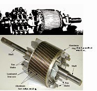
Squirrel Cage Rotor

Squirrel Cage Rotor

Construction (Stator construction)


•          The stator is the stationary electrical part of the motor.
•          The stator core of a National Electrical Manufacturers Association (NEMA) motor is made up of several hundred thin laminations.
•          Stator laminations are stacked together forming a hollow cylinder. Coils of insulated wire are inserted into slots of the stator core.
•          Electromagnetism is the principle behind motor operation. Each grouping of coils, together with the steel core it surrounds, form an electromagnet. The stator windings are connected directly to the power source.

Construction (Stator construction)

Construction (Rotor construction)


•          The rotor is the rotating part of the electromagnetic circuit.
•          It can be found in two types:
–        Squirrel cage
–        Wound rotor
•          However, the most common type of rotor is the “squirrel cage” rotor.

 Construction (Rotor construction)

•          Induction motor types:
v                  Squirrel cage type:
Ø  Rotor winding is composed of copper bars embedded in the rotor slots and shorted at both end by end rings
Ø  Simple, low cost, robust, low maintenance
v   Wound rotor type:
Ø  Rotor winding is wound by wires. The winding terminals can be connected to external circuits through slip rings and brushes.
Ø  Easy to control speed, more expensive.

Construction (Rotor construction)


Wound Rotor

Wound Rotor


Squirrel-Cage Rotor


Squirrel-Cage Rotor


Construction (Enclosure)


•          The enclosure consists of a frame (or yoke) and two end brackets (or bearing housings). The stator is mounted inside the frame. The rotor fits inside the stator with a slight air gap separating it from the stator. There is NO direct physical connection between the rotor and the stator.

Construction (Enclosure)


•          The enclosure also protects the electrical and operating parts of the motor from harmful effects of the environment in which the motor operates. Bearings, mounted on the shaft, support the rotor and allow it to turn. A fan, also mounted on the shaft, is used on the motor shown below for cooling.

Construction (Enclosure)

Construction (Enclosure)


Nameplate Data

Nameplate Data

Manufacturer’s Type


Manufacturer’s Type


Rated Voltage


Rated Voltage


FLA(Full Load Amps)


FLA(Full Load Amps)


Rated Frequency


Rated Frequency


Full Load RPM


Full Load RPM


Insulation Class


Insulation Class


Ambient Temperature


Ambient Temperature

Time Rating(Duty)


Time Rating(Duty)


Horsepower Rating


 Horsepower Rating


Locked Rotor kVA Code


Locked Rotor kVA Code


Power Factor


Power Factor


Service Factor


Service Factor


Enclosure Type


Enclosure Type


Nominal Efficiency


Nominal Efficiency


Frame Size


Frame Size


NEMA Design Letters


NEMA Design Letters


Rotating Magnetic Field


•          When a 3 phase stator winding is connected to a 3 phase voltage supply, 3 phase current will flow in the windings, which also will induced 3 phase flux in the stator.
•          These flux will rotate at a speed called a Synchronous Speed, ns. The flux is called as Rotating magnetic Field
•          Synchronous speed: speed of rotating flux

 Where;                 p = is the number of poles, and
                                                f  = the frequency of supply

Rotating Magnetic Field

AC Machine Stator

AC Machine Stator


Slip and Rotor Speed


•          The synchronous speed for a squirrel cage motor is calculated by multiplying the constant 120 times the electrical supply frequency; then dividing the result by the number of poles in the motor.
Synchronous speed = 120(frequency)
                                        no. of poles

Slip and Rotor Speed


The actual speed of a squirrel cage motor is less than its synchronous speed. This difference between actual speed and synchronous speed is called "slip.“

                                                                slip%= (syn-actual)(100)
                                                                                        sync

Slip and Rotor Speed


The design of a motor stator and rotor affect its slip characteristics. Squirrel cage motors are made with slip ranging from less than 5% to more than 20%. Motors with slip less than 5% are sometimes called normal slip motors. Motors with slips greater than 5% are used for hard to start loads, because of their inherent capability to create more torque.

Asynchronous and Synchronous Motor


In a typical AC motor, a rotating magnetic field is produced in the stator. The speed of this rotating field is called the synchronous speed and is determined only by the frequency of the power supply and the number of poles of the machine. A synchronous motor is one in which the rotor rotates at the same speed as the rotating magnetic field in the stator. An asynchronous motor is one in which the rotor rotates at a speed slower than the synchronous speed.

 Principle of Operation


Ø  When a 3 phase stator winding is connected to a 3 phase voltage supply, 3 phase current will flow in the windings, hence the stator is energized.
Ø  A rotating flux Φ is produced in the air gap. The flux Φ induces a voltage in the rotor winding (like a transformer).
Ø  The induced voltage produces rotor current, if rotor circuit is closed.
Ø  The rotor current interacts with the flux Φ, producing torque. The rotor rotates in the direction of the rotating flux.
Share:

Wednesday, 16 March 2016

Delayed Automatic Forward Reverse Motion of Overhead Crane Driven by a Motor


This is another situation that requires the overhead crane to rest for a while upon reaching both of the rail. After a pre-determine time the overhead crane will re-start in the opposite direction.

The control circuit of this system is shown in Figure 8. Two times TR1 and TR2 are connected to the limit switches Y and X respectively at terminal 3.

The terminal no. 1 of the instantaneous contacts TR1(1-3) and TR2(1-3) are connected to the terminals no. 3 of the limit switch Y and X respectively. The delay contact TR1(6-8) and TR2(6-8) are connected to the contacts R(13-14) and F(13-14) respectively.


Delayed Automatic Forward Reverse Motion of Overhead Crane Driven by a Motor


Supposing the overhead crane is moving in the forward (right) direction that means, contactor F(A-B) is at energized and contactor R(A-b) is at de-energize condition. When the overhead crane reaches the right end limit and touches the limit switch Y, the contact Y(1-2) of limit switch Y will open to de-energize contactor F(A-B). This will bring the overhead crane to stop moving in the forward right direction and it will remain at stand still for a pre-determine time set by timer TR1. Also the contact Y(1-3) of the Y limit switch will close to de-energize timer TR1. The instantaneous contact TR1(1-3) will close instantly to maintain TR1 continously energized.

After the pre-determine time set by TR1, the delay contact TR1(6-8) will close to energized contactor R(A-B). This will cause the overhead to start moving in the reverse (left) direction. At this point the connection of limit switch Y contacts Y(1-2) will open and contact Y(1-3) will close.

When the overhead crane reaches the left and it touches the limit switch X, the contact X(1-2) of limit switch X will open to de-energized contactor R and timer TR1. Instantaneous contact TR1(1-3) will open. At this point the overhead crane will stop moving in the reverse (left) direction and it will remain at stand still for pre-determine time set by timer TR2. Also the contact X(1-3) of the X limit will close to energized timer TR2. The instantaneous contact TR2(1-3) will close instantly to maintain TR2 continuosly energized. After the pre-determine time set by timer TR2, the delay contact TR2(6-8) will close to energize contactor F(A-B).

When the contactor F(A-B) is energized, it will cause the overhead crane to start moving in the forward (right) direction. Immediately after, the connection of contact X(1-3) will open and contact X(1-2) will close again. Timer TR2 will remain energize because its instantaneous contact TR2(1-3) is maintain close. Timer TR2 will be de-energized when the overhead crane reach the right end limit and touches limit switch Y. 

Share:

Automatic Forward and Reverse Motion of Overhead Crane Driven by a Motor

Notice that when contact (1-2) of limit switch X opens to de-energized contactor F, its contact (1-3) will almost simultaneously closed to energized the contactor R. This will bring about the automatic reversal of the overhead crane from the left to the right. 


Automatic Forward and Reverse Motion of Overhead Crane Driven by a Motor

On the other hand where contact (1-2) of limit switch Y opens to de-energized contactor R, its contact (1-3) will almost simultaneously closed to energize the contactor F. This will bring about the automatic reversal of the overhead crane from the left to the right.


Next Article: Delayed Automatic Forward Reverse Motion of Overhead Crane Driven by a Motor  
Share:

Limiting the Forward and Reverse Motion of an overhead crane driven by a motor


The motion of an overhead crane moving forward and reverse can be automatically stop at both end by placing a limit switches X and Y in the control circuit of the Forward – Reverse Motor Control shown in Figure below (d).

Refer to Figure below (d). When contractor F is energized, the motor runs clockwise. The motor drives the overhead crane to move the right (forward) direction as shown in Forward Reverse Motor Control . Before the crane could reach the right end wall, it will hit the Limit switch X. Limit switch X will open its normally closed contact X(1-2) to de-energized contactor F. With contractor F de-energized. The overhead crane will stop and it will never have a chance to hit the right end wall. Pressing the forward push button will never make the motor run and the overhead crane remains immobilized.


Limiting the Forward and Reverse Motion of an overhead crane driven by a motor

However, pressing the reversed push button will energized contractor R and will enable the motor to run in counterclockwise direction. The motor will drive the overhead crane to move to the left (reverse) direction. Before the crane could reach the left end wall, it will hit the limit switch Y. Limit switch Y will open its normally closed contact (1-2) and de-energized contactor R. With contractor R de-energized, the overhead crane will stop and prevented from hitting the wall at the left end. Pressing the reverse push button will never make the motor run and will render the overhead crane immobilized.


                The motion of an overhead crane shown in Figure above (d) can be automatically change to opposite direction when it reaches both end, that is hitting the limit switch X and Y without pressing the forward and reverse push button switches any longer. This can be done by connecting terminal 3 of limit switch X to terminal 11 of contact F(11-12). And connecting the terminal 3 of limit switch Y to terminal 11 of contact R(11-12), see Next Article: Automatic Forward and Reverse Motion
Share:

Monday, 14 March 2016

Forward Reverse Motor Control


The forward reverse motor control is used i a system where forward and backward or upward and downward movement in the operation are needed.

An example of which are shown in figures below (a) and (b). Figure below (a) shows forward and backward lateral movement of an overhead crane driven by motor M. Figure below (b) shows a downward and upward movement of a load is driven by motor lifter M.


(a) Lateral movement of an overhead crane driven by a motor.

   
  (b) Vertical movement of a lift by a motor.


Control Operation

      The clockwise (forward) and counterclockwise (reverse) rotation of a motor can be caused by interchanging the connection of any of the two of its three terminals. Figures (c) and (d) below will show how this can be done.
Contractors F and R are interlocked. It means that if the contacts (1-2, 3-4, 5-6) of contractor R can not be closed. On the other hand if  the contacts (1-2, 3-4, 5-6) of contractor R are closed, contacts (1-2, 3-4, 5-6) of contractor F can not be closed. 


        Note that when the contacts of contractor F in Figure (a) are closed, L1 is connected to T1 through contact F (1-2), L2 is connected to T2 through contact F(3-4), and L3 is connected to T3 through contact R(5-6).The motor M will run forward. 

        When the contacts of contractor R in the Figure (a) are closed, L1 is connected to T3 through contact R (1-2), L2 is connected to T2 through contact R(3-4) and L3 is connected to T1 through contact R(5-6). The motor M will run reverse.


        Referring to the control circuit on Figure (a), pressing the forward push button F will energize contactor F. Maintaining contact F (13 14) will close to maintain contact or F continually energized even if the forward push button is release. Contactor F (11-12) will open to prevent contactor R to be energized. Contacts F(1-2, 3-4, 5-6) will close to run motor M on forward direction.


       Pressing the stop push button will de-energized contactor F. This will cause the contacts R(1-2, 3-4, 5-6) to open and stops the motor M from running forward. Contacts F(11-12) will close again. Maintaining contact F(13-14) will open.  


       Pressing the reverse push button R will energize contactor R. Maintaining contact R(13-14) will close to maintain contactor R continually energize evenif the reverse push R button  is release. Contacts R(11-12) will open to prevent contactor F to be energized. Contacts R (1-2, 3-4, 5-6) will close to run motor M on reverse  direction.


     Pressing the stop push button again will de-energized contactor R. This will cause the contacts R(1-2, 3-4, 5-6) to open and stops the motor from running reverse. Contact R(11-12) will close again. Maintaining contact R(13-14) will open. This brings the condition of the circuit the same as the one shown in Figures (a) and (b) below.  

(a) Control circuit of Forward – Reverse Motor Control with limit switches X and Y.


(b) Power circuit of Forward Reverse. 


(c) Connection of Motor to power lines at forward condition.


 (d) Connection of Motor to power lines at reverse condition.


Share:

Saturday, 12 March 2016

WYE-DELTA REDUCE VOLTAGE STARTER


Some motors starters at high current more than several times its current at full load condition. The effect of this to other is necessary tripping of circuit breakers.
          One way of reducing the high starting current of a motor is the start the motor with the low voltage at its winding. After a few seconds, when the motor is already running at its stable condition, the rated full voltage is applied to its winding. This system is called reduced voltage starting.
          One method of reducing the starting current of a motor is to connect the winding of the motor into WYE connection during the starting process and when the motor is running, the winding are connected into Delta, see figures 9(c) and (d). Note that at WYE connection the voltage across the motor windings is 220 volts, Figure below (d).


CONTROL OPERATION


Figure below(a) and (b) shows the power and control circuit of a “WYE-DELTA Reduced Voltage Starter”. A time delay relay (Timer) is in the control circuit. The timer TR will delay the opening and closing of its normally closed contact TR (8-5) and normally open TR (8-6) respectively when its coil terminals TR (2-7) is energized, the duration of delaying I set by adjusting a knob in the timer TR.

          Referring to figures below (a) and (b), pressing the start push button will energized M1 contactor, timer TR, delay relay, and S contactor. Contactor M1 (13-14) will closed to maintain control circuit. Contact S (11-12) will open to prevent unnecessary energizing of contact motor M2. Contacts M1 (1-2,3-4,5-6) and S (1-2,3-4,5-6) will closed simultaneously to connect the motor windings (T1-T4,T2-T5,T3-T6) into WYE connection see figure below (c).

After a few seconds the normally closed the normally closed contact TR (8-5) will open and normally open contact TR (8-6) will close. Contactor S will be de-energized to open its contacts S (1-2,3-4,5-6) and closed its contact S (11-12). Also contactor M2 is energized when TR (8-6) closes. Contacts M1 (1-2,3-4,5-6) will closed. At this contacts M1 (1-2,3-4,5-6) remains closed. At this condition the motor winding (T1-T4,T2-T5,T3-T6) is change into delta connection as shown in figure below (d).

          Pressing the Stop push button will de- energized contactor M1,timer TR, and contactor M2. This will bring the motor into halt.


(a) Control Circuit of the WYE-DELTA starter.


Control Circuit of the WYE-DELTA starter


(b) Power Circuit of the WYE-DELTA starter.


Power Circuit of the WYE-DELTA starter.


(c) WYE connection of the motor windings.


WYE connection of the motor windings.


(d) Delta connection of the motor winding.


Delta connection of the motor winding.
 
Share:
Powered by Blogger.